Finding myself stuck at home more during the pandemic, one hobby I’ve focused on is robotics. Many of my projects run on batteries and some need to intelligently realize that the charge is running low so that they can take shutdown steps prior to disconnecting the battery.
I’ll also be the first to admit that batteries, particularly LiPos, are not my strong suit and kinda freak me out. I guess I’ve watched one too many YouTube videos….
I present here my design for a LiPo undervoltage detection and protection circuit, controlled by a microcontroller (μC). I take no responsibility for any issues, so if you decide to use it, you do so at your own risk. And I certainly welcome feedback: you can find me on Twitter @RobBotic.
I did look for COTS solutions, but unfortunately none that I could find would leave the decision making to a μC. And who can pass up a good learning opportunity?!?
Here are my goals and requirements for this circuit:
- Reusable design for many projects.
- Works with my LiPo battery, which is a 3S (~9.6 – ~12.6V) 5000mAh 20C pack (~100A), but oddly has an XT60 connector, which limits it to 60A. Plenty for me though….
- Provides undervoltage protection, as these batteries should not be discharged below a certain level. Further, I’d prefer that the circuit completely disconnect, to prevent additional current drain. That way, if I do not unplug the battery right away, it is less of an issue (many protection circuits simply use transistors to disconnect the battery, which still has some current drain).
- Reverse polarity protection (though with an XT60 connector it will be quite difficult to plug in incorrectly).
- μC-controlled disconnect. Given one of my projects is a self-balancing robot, it needs to perform a shutdown sequence (put out a kickstand) prior to disconnecting the battery so that it does not fall on its face. Ideally this will work with the μC or single board computer of your choice, such as an Arduino or Raspberry Pi.
- Largely failsafe. In the event of a short, a μC crash, etc., I’d like the battery to be disconnected.
To operate, a user presses a START button (PBSW1 below), which will power the μC. The μC then samples a voltage divider and determines whether to close a relay. The μC will enter a shutdown sequence (and eventually open the relay / stop powering the relay coil) should the voltage level drop enough in the voltage divider or should a STOP button (PBSW2 below) be pressed.
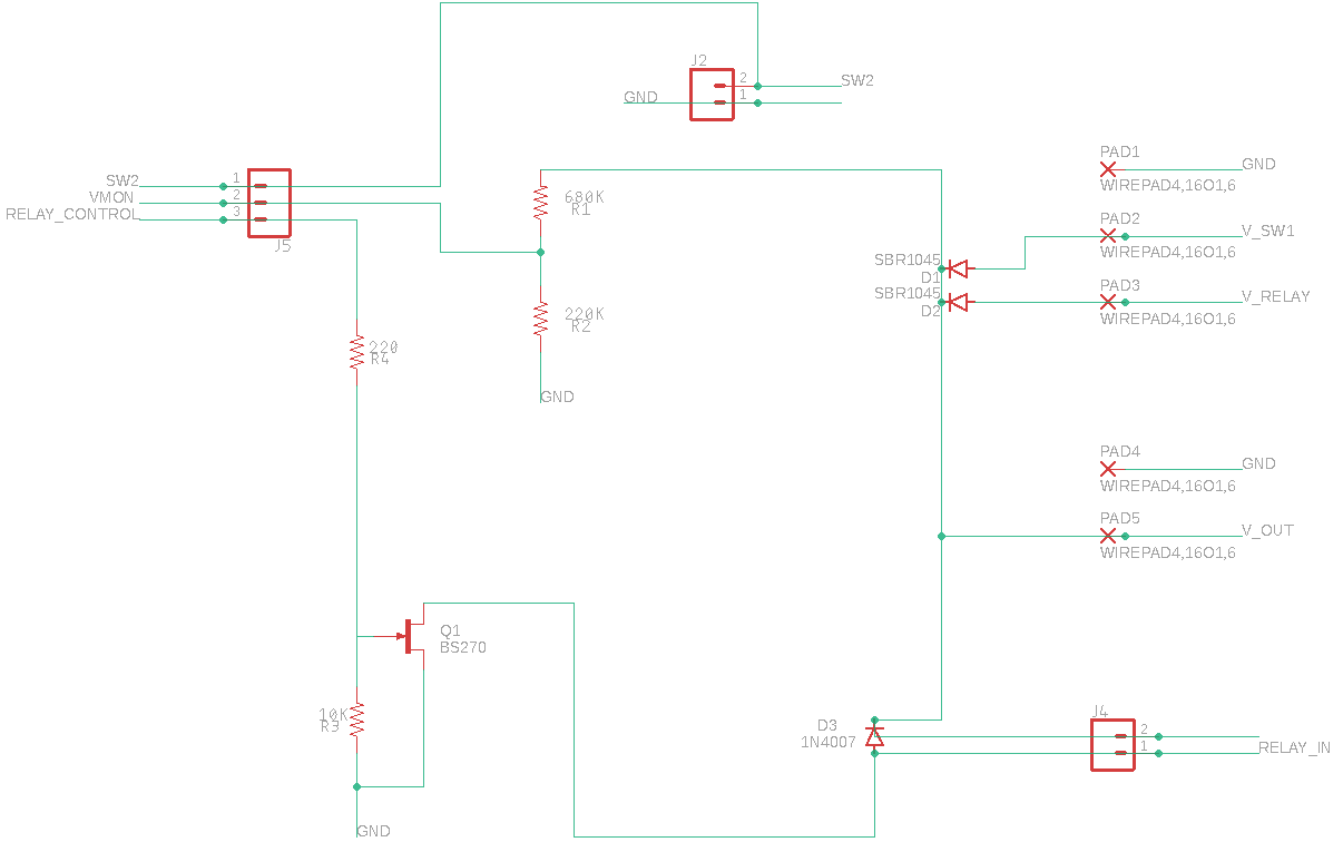
And this is the resulting circuit, both hand drawn and created in EAGLE:
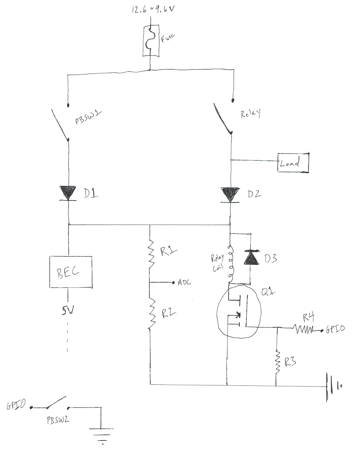
- BEC
- This is simply a buck converter / voltage regulator. It turns out that the RC world calls them BECs (or SBECs or UBECs) and has a pretty good range of robust pieces available. I grabbed this Turnigy UBEC. It is probably overkill at 8A, but I may need some servos on the 5V side.
- Fuse
- I went with a 60A automotive fuse and soldered on XT60 connectors.
- Relay
- Once again, I went down the automotive route and used an automotive relay capable of handling a current in excess of 60A. This relay is closed to enable the battery to power both the μC as well as the load.
- PBSW1
- Momentary switch (normally open) to start the circuit. This switch was chosen to handle the current drawn by the μC, etc., but not the load.
- PBSW2
- Momentary switch (normally closed) to stop the circuit. The μC monitors this switch for a user request to start the shutdown sequence.
- R1 and R2
- Voltage divider. The values were chosen to drop the 3S LiPo voltage down to a reasonable level for a 3.3V analog input on the μC. The μC monitors this voltage and starts a shutdown sequence when the voltage falls below a threshold. Similarly, the μC will only close the relay if the voltage is above a (slightly higher for hysteresis) threshold.
- R3
- Pulldown resistor.
- R4
- I’ve read that this resistor may not be necessary with a MOSFET, but better safe than sorry.
- D1
- Reverse polarity protection, conveniently with the same voltage drop as D2. Note that I only need reverse polarity protection here, as the circuit is always initially powered on this side.
- D2
- Protects PBSW1 from the load current. Thus, the load is only powered via the relay and not when PBSW1 is pressed.
- D3
- Flyback diode.
- Q1
- N-channel MOSFET. I went with a logic-level MOSFET instead of the more common BJT to minimize the current, as Q1 is always energized while the relay is closed. The μC outputs to Q1 to close the relay / power the relay coil, as the μC itself cannot provide the current required to close the relay. Note that I went with a BS270 here, but will likely reevaluate that decision in the near future, as the BS270 works well for 5V logic, but not 3.3V logic.
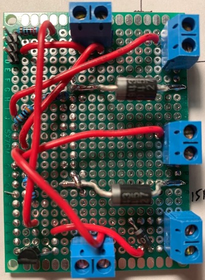
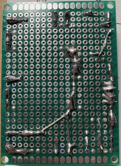
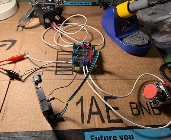
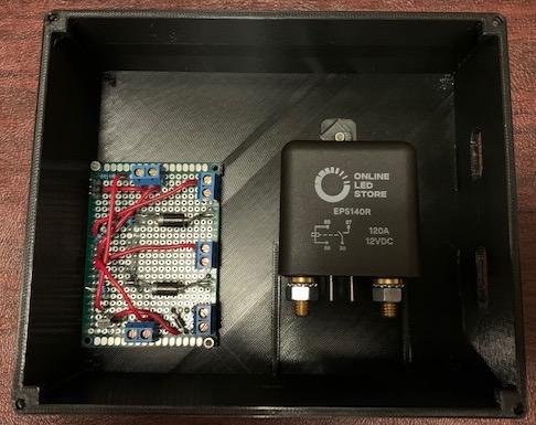
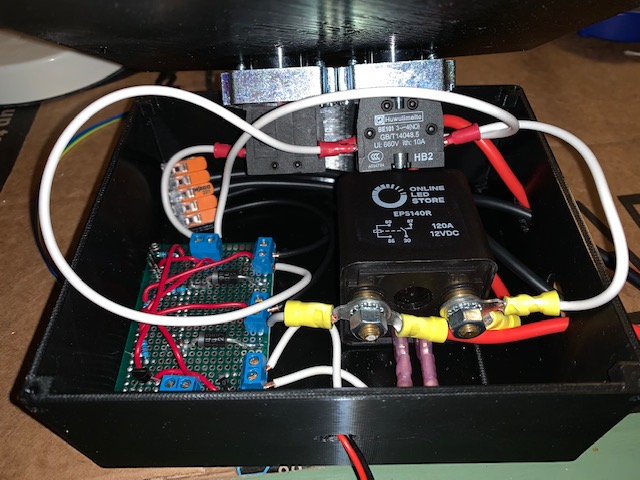
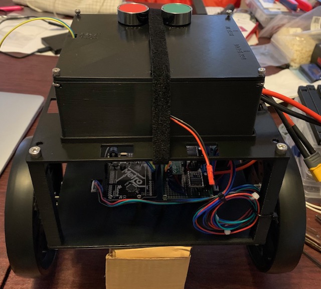
And here is the resulting make, complete with my not-so-great soldering skills and a 3D-printed box (printed with my beloved Prusa I3 MK3S):